44, JFET Common Gate Amplifiers
Cliquez pour afficher sur Bing31:29
9-1: The Common Source Amplifier JFET Amplifier Operation In common source self biased amplifier Vin is applied to the gate and Vout is taken from the drain as shown with phase difference between them 180° Remember that for ac signal capacitors are short and VDD is ac ground Æ source terminal S and RD are connected to the round in ac equivalent circuit
Common-Gate FET Amplifiers
The Common Gate Amplifier: Same Topology Different Look The gate terminal is “common” between the input and the output The common gate amplifiers are useful when small input resistances and large output resistances are desired in amplifiers But the current gain is unity! Note: The bulk is not tied to the source IBIAS Assume an + AC short S-VBIAS
COMMON SOURCE JFET AMPLIFIER
This video covers the characteristics of JFET Common Gate Amplifiers, The DC and AC parameters are analyzed and a circuit based on the values used in the sc
Common Source JFET Amplifier – ALL ABOUT ELECTRONICS
fet common-source amplifier biasing-graphical method #1 1, find v gsoff & i dss for your device; measure using curve tracer, [v gsoff = gate-source voltage for which i d = 0, i dss = i d when v gs = 0] 2, assume r s << r l, 3, plot a load line on the output characteristics, keep the i d, v ds = 0
Lecture 12 Single Stage FET Amplifiers: Common Gate
Fichier PDF
Common gate
Overview
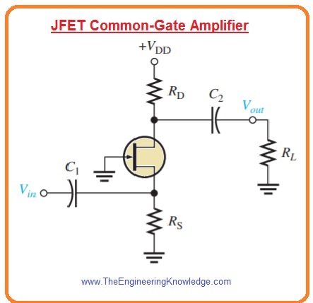
The common gate field effect amplifier configuration is associated with the common base configuration of BJT, Similar to the common base arrangement the input resistance of common gate is also less, It is different to the common source and common drain configurations that have a large value of input resistances,
FET common gate amplifier is used to provide low input impedance or high isolation between input & output to stop oscillation etc, The FET common gate amplifier circuit is the least widely used but it does possess some characteristics that can be put to good use in some applications,
Likewise in Transistors, JFET amplifiers can also be setup in the three configurations namely, Common Drain, Common Source and Common Gate, Transistor Configurations; Common source configuration is almost similar to Common emitter configuration of BJT’s Common Emitter RC Coupled Amplifier, JFET can also be biased as Voltage Divider or Self Bias, COMMON SOURCE …
AMP I,12 – The Common Gate Amplifier
Introduction
FET Common Gate: Amplifier Circuit » Electronics Notes
Analog Electronics: Common-Gate Configuration of JFETTopics Discussed:1, Common-gate configuration construction,2, Transfer curve plot of JFET,3, Load line4,
common gate jfet amplifier
We said previously that the input current, Ig of a common source JFET amplifier is very small because of the extremely high gate impedance, Rg, A common source JFET amplifier therefore has a very good ratio between its input and output impedances and for any amount of output current, Io the JFET amplifier will have very high current gain Ai, Because of this common source JFET …
Chapter 9: FET Amplifiers And Switching Circuits
Fichier PDF
Common Source JFET Amplifier
The Common Source JFET junction field-effect transistor Amplifier circuits usages JFET as their chief energetic component for delivering higher input impedance appearances, Mostly signal amplifier circuits are made by bipolar junction transistors like common-emitter transistors, but where a small signal has to amplify where FET is used as an amplifier,
Common-Gate Configuration of JFET
The input signal Vin of the common source JFET amplifier is applied between the Gate terminal and the zero volts rail 0v With a constant value of gate voltage Vg applied the JFET operates within its “Ohmic region” acting like a linear resistive device The drain circuit contains the load resistor Rd The output voltage, Vout is developed across this load resistance,
Common Source JFET Amplifier
JFET AMPLIFIER CONFIGURATIONS
Fichier PDF